|
Step 4: Splicing into the ECU wires
Now its time to splice into
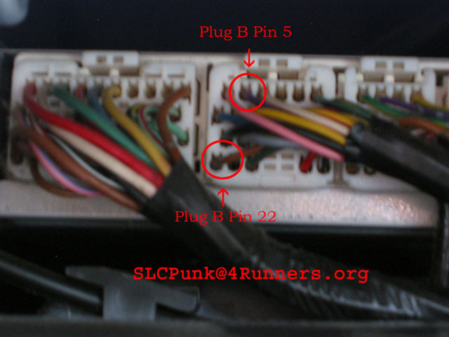
the ecu wires. In my case, I had to locate Plug B Pin 22 (brown with black stripe)
and Plug D Pin 22 (white with blue stripe).

|
| Prepare TMC wires by crimping ends. Plug D Pin 22 |
|
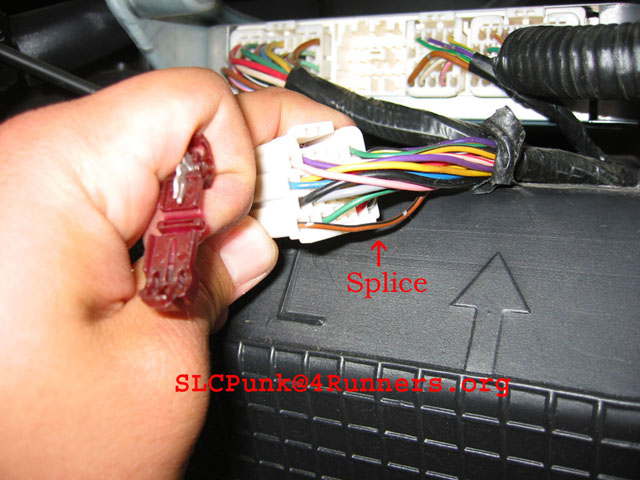
| Plug B 22 is spliced. Plug B Pin 5 will be used in step 5 |
To tap into the wires, using the supplied wire-taps you will need to
get working space. I cut away approx 1½” of tape out of my way. Then installed the tap approx 1” from the harness. Line
up the tap and wire and use your wire crimper to press the tap into the wire. Now
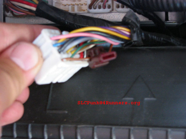
you will need to crimp the male connector to the TMC 1.1 wires to connect it to the wire splice.
Do this step two times, once for the TMC 1.1’s white with black
stripe wire and once for the red wire.
|
| Plug B Pin 22 |
|
| Plug D Pin 22 |
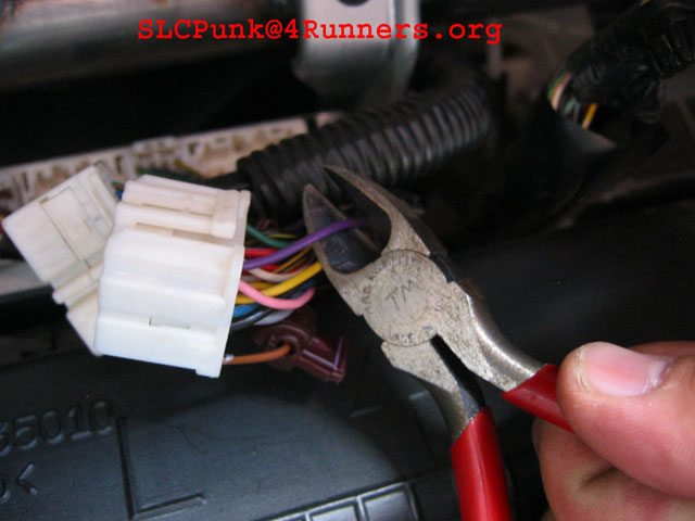
Step 5: Cutting/reconnecting sensor wire
Now its time to cut the wire
from the sensor to the ecu harness. In my application it is a purple wire, but
yours may differ (see illustration above). Refer to the Split Second instructions. I cut the factory tape and cleared myself approx 2” of wire. I cut the wire 1” from the harness. The green w/red
stripe wire goes into the ecu and the green wire goes from the sensor to the TMC 1.1.
After you crimp the wires, the split second connectors have heat-shrink ends to keep the wire ends clean. You should use a heat gun and shrink the ends down, but I used a lighter to do this. *Be careful; do not burn the wire, heat shrink or your entire vehicle!!
|
| Picture of the wire that is cut. |
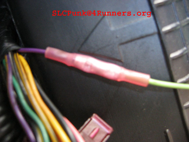
|
| Picture of the connectors and the heat shrink. |
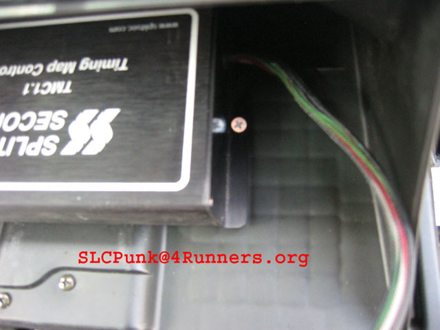
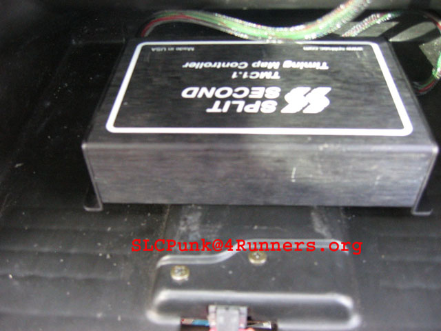
Step 6: Install the TMC 1.1 Unit
Secure the wires and install the TMC 1.1. I used two
short self-tapping screws to install the TMC 1.1 into the glove box. I barely
drilled a hole (just enough to get the screw started) into the interior panel of the glove box. Then install the screws.

Step 7: Reinstall the Glove box interior panel
Reinstall the wire clips and wire harnesses to the glove box panel. Bolt up the panel and re-install the glove box and hook up the battery.
|